New Version - NX 2007
4594 Views |

Edited by Sorawit Tangjai – Application Engineer, ISID South East Asia
12/20/2021
What’s New in NX – NX 2007
1) NX 2007: Interface
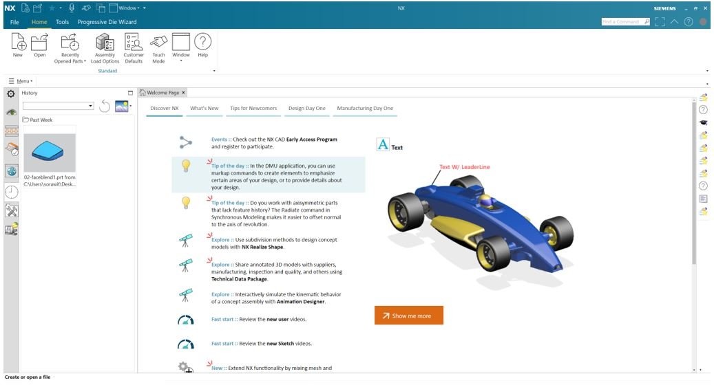
Figure 1: NX 2007 Interface – provides a lot of assistances and basic training that will help users to understand more about features and tools in NX, and up-to-date feature such as what’s new, tips for newcomers, design day one, and manufacturing day one.
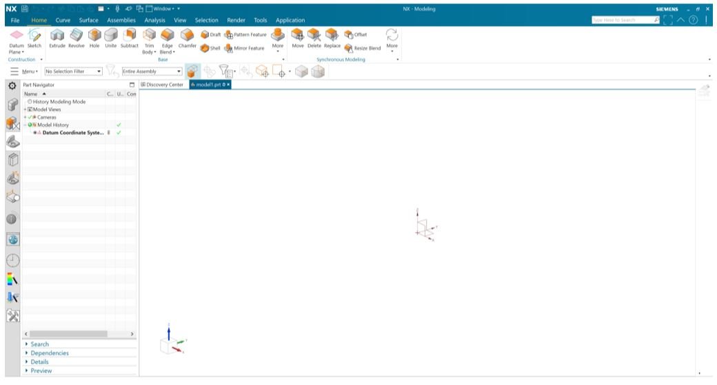
Figure 2: NX 2007 Interface – Home Menu
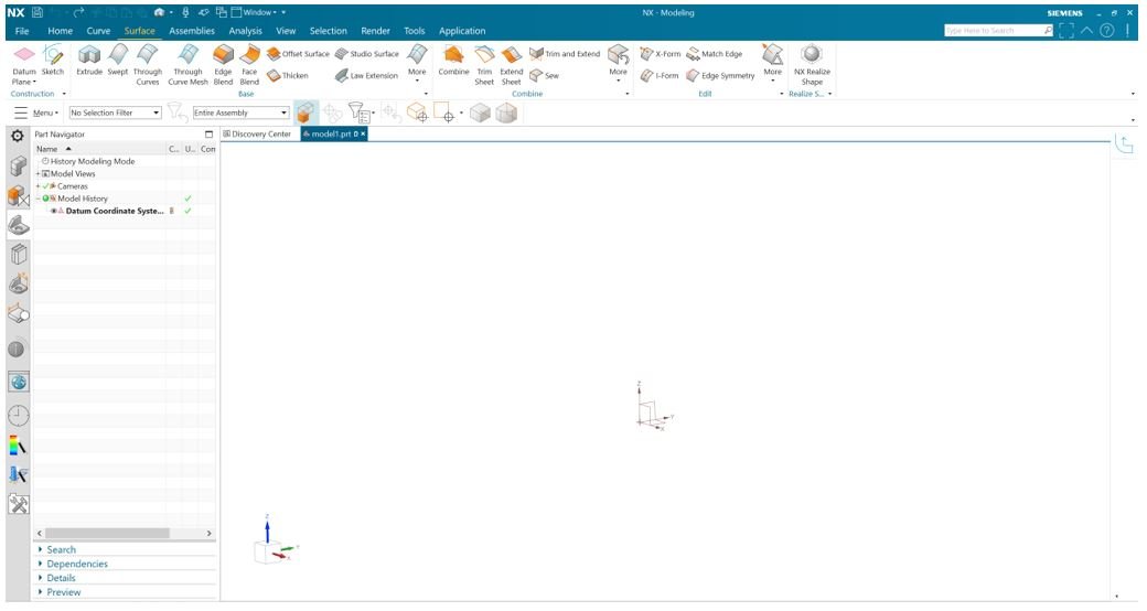 Figure 3: NX 2007 Interface – Surface Menu
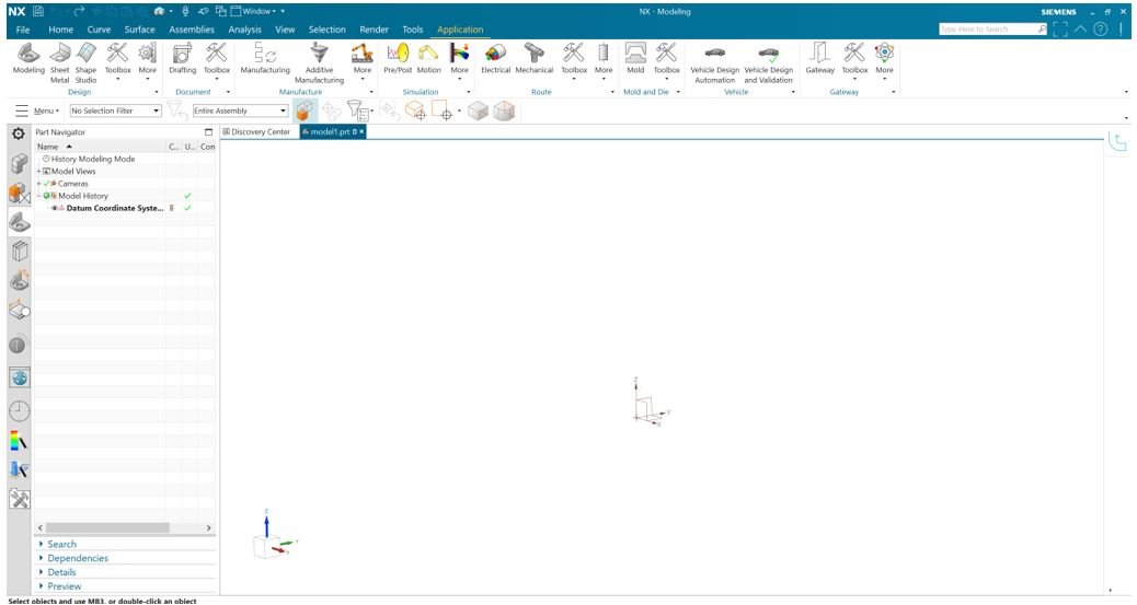 Figure 4: NX 2007 Interface – Application Menu
2) Legacy commands and commands to be retired – Commands that have (Legacy) or (to be retired) in their name are outdated, unsupported commands. In many cases, newer commands that provide more robust and enhanced functionality or support improved workflows, exist. Legacy commands remain in NX to sustain legacy workflows and products. Commands to be retired will be removed in a future version if NX, typically within two to four NX version.
Retired commands in NX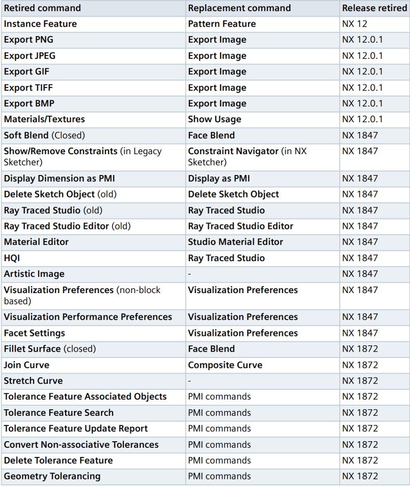
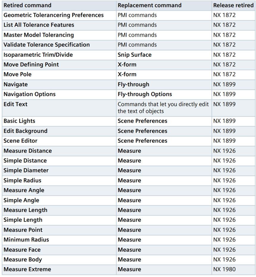
Figure 5: List of all retired features
3) NX 2007 Update
a. Design and simulation are more integrated than ever through several new and improved product capabilities in the areas of topology optimization, design space exploration, and simulation driven structures optimization
b. New, more powerful and more automated structures design capability through algorithmic, lattice, and implicit modeling improvements
c. Greater ability to edit multi-cad and legacy product data through synchronous modeling improvements
d. Improved engineering workflow robustness through improved methods to heal imported surface data
e. More efficient 2D based modeling capabilities through sketching and revolved outline improvements
4) NX 2007 Sketch - Sketch onboarding for legacy sketch users shortens transition time to the new sketching environment
NX will be rolling out a series of new videos to be watch targeting toward legacy sketch users throughout the EAP cycle
Available videos in First Help include:
a. New help topics to explain and show different workflows comparing the legacy sketcher to the new sketcher
b. Topics determined from feedback of transitioning users
c. Start with a video or two and continue rollout during EAP
d. Please provide feedback on content and additional topics you would like to see
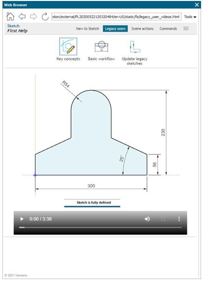
Figure 6: NX 2007 Sketch – New sketch helper provides video
Sketch display dimension as diameter allows customers to easily document revolved sections:
Sketch now offers the ability to create and display "half-dimensions" and display as a diameter
a) Powerful new dimensioning function in Sketcher
b) Highly requested customer enhancement (21 ERs)
c) Allows for easier documentation of revolved sections – define the diameter and not the radius
d) Create dimension, use RMB "Convert to Half Dimension"
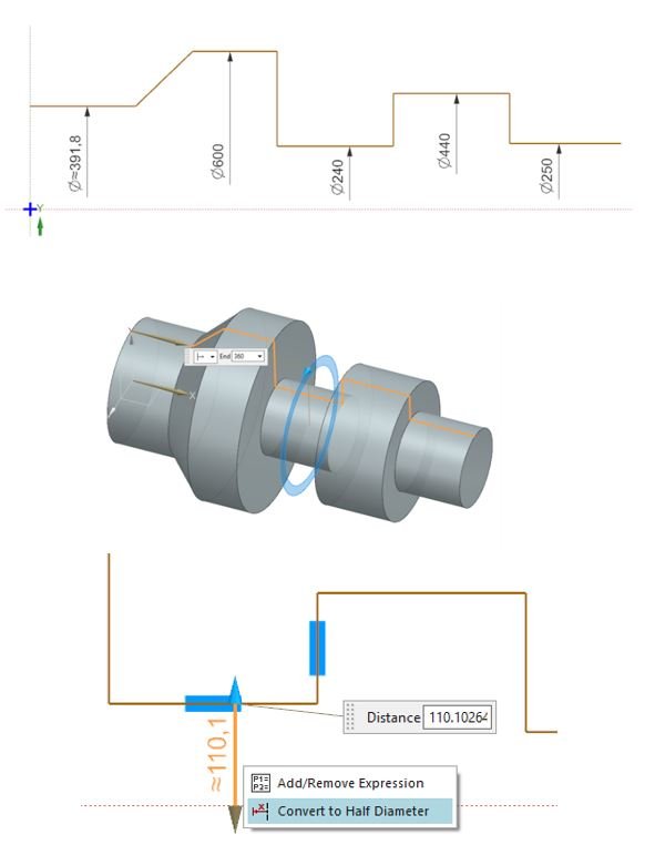 Figure 7: NX 2007 Sketch – New sketch display dimension
5) NX 2007 Synchronous Modeling – New clone finding technology added to several synchronous modeling commands to greatly speed up selection of like entities
Enabling selection of identical objects throughout the model is a major productivity enhancement
With a single selection NX will find clone entities that exist on the part, proximity sensitivity can be adjusted to include more/less objects in the selection
Enhanced commands include:
· Move Face, Delete Face, Resize Hole, Resize Blend, Pattern Face
· Face Finder added to Delete Face and Resize Hole
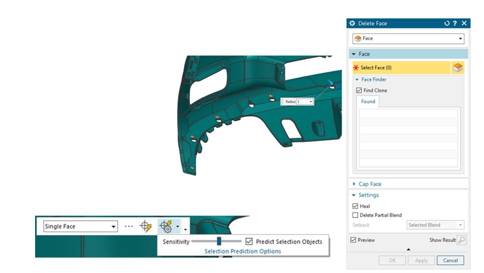
Figure 8: NX 2007 Synchronous Modeling – this is the example of a new resize hole feature that will automatically find like entities by selecting Predict Selection Object and adjust sensitivity of its detection to pick the similar objects in which you can easily change the property in a larger group with less time
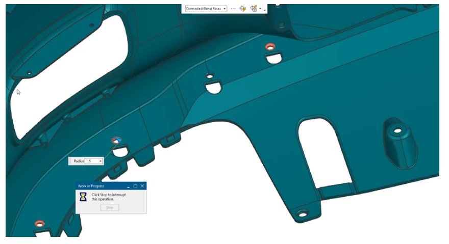
Figure 9: NX 2007 Synchronous Modeling – shows the new synchronous technology with resize hole feature detecting like entities
6) NX 2007 Feature Modeling – Manual thread input option enables the creation of non-standard thread sizes
Input of user-generated Custom Thread sizes are now available
NX now offers 2 methods for creating custom thread sizes: ../../UGII/modeling_standards/NX_Thread_Standard.xml, or direct entry on Thread form (NEW!)
· Customer requested return of Manual Thread input during Symbolic or Detailed Thread creation
· Users do not need to modify thread .xml to add standard threads
· When using Thread Table with Radial Engage set to custom, Tap Drill Size can be user defined
· Now supporting renew of legacy Manual Threads
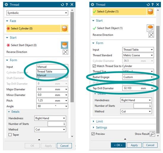
Figure 10: NX 2007 Feature Modeling – shows the new custom input option
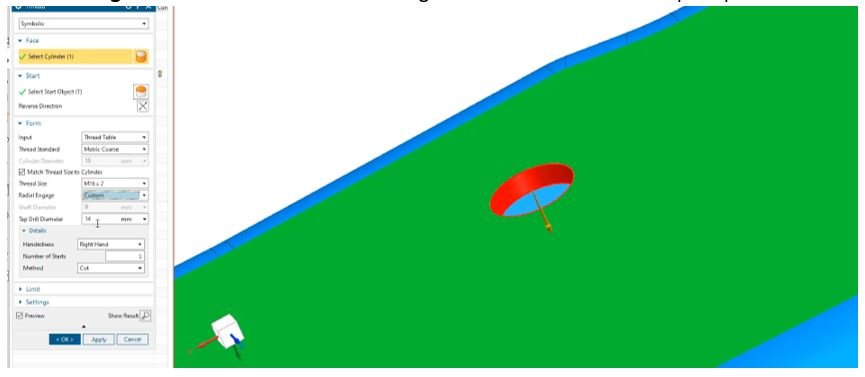
Figure 11: NX 2007 Feature Modeling – applies non-standard thread option to the hole
History free modeling mode is back for quick concepting and protection of intellectual property
History Free modeling allows for the use of all modeling functionality without creating the feature tree in the Part Navigator
Capabilities include:
· History Free mode does not create features
· Activated through RMB on the Part Navigator Modeling Mode designation
· When activating History Free any features that already exist will be removed from the model
· When activating History Free an informational message is displayed to inform the user
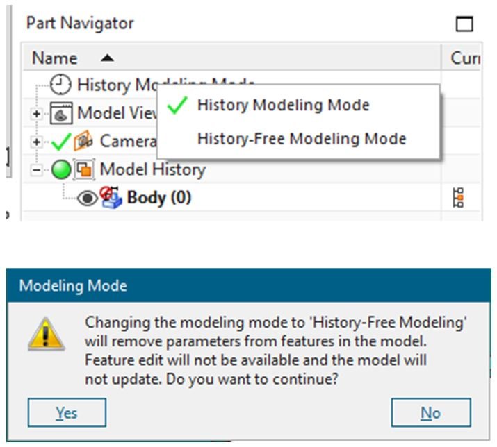
Figure 12: NX 2007 Feature Modeling History Free Mode with no worries on previous model history
New functionality in compare body allows for more comparison options and added productivity
New options have been added to both Face and Distance Map Comparison Methods
Capabilities include:
· New Deviation Face Comparison Method
· Deviation Floor option allows user to only see differences above a selected value
· Deviation dimension added to display to show areas of concern
· Tessellation Tolerance added to Distance Map Comparison Method for more granular control of the results display
 Figure 13: NX 2007 Feature Modeling Compare Body – new deviation face comparison feature is added to display areas of concerns
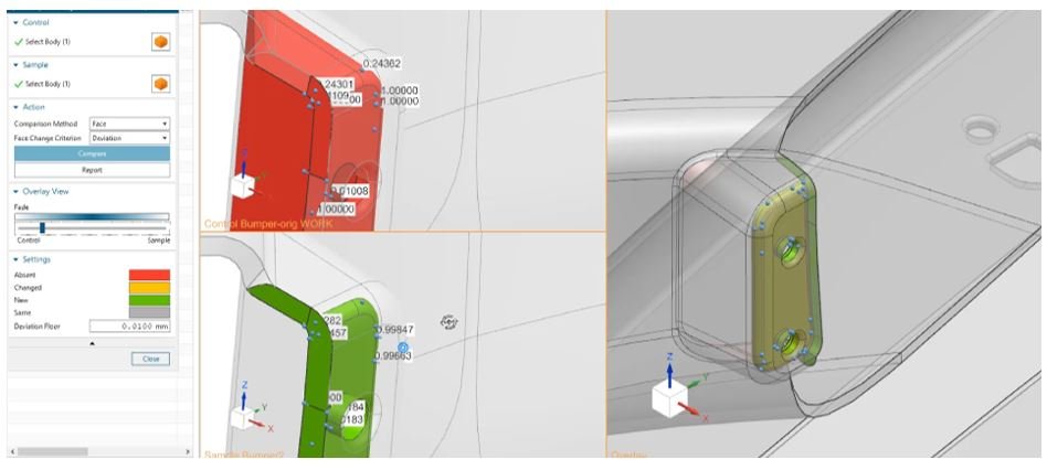
Figure 14: NX 2007 Feature Modeling Compare Body – shows areas of deviation dimension after compare 2 bodies
Create a fully associative 2D outline in of a complicated spun shape in a single step
Powerful capability to support turbo machinery design workflows
Revolve Outline automates the process of creating 2D representations used for design reviews and 2D analysis
· A maximum 2D envelope is created by combining axisymmetric and non-axisymmetric (e.g. turbine blades, holes, etc.) features onto a plane
· Supports the selection of a body or multiple bodies (including inter-part selection)
· Exclusion faces can be defined

Figure 15: NX 2007 Feature Modeling 2D Outline– show areas of created 2D Outline using Revolve Outline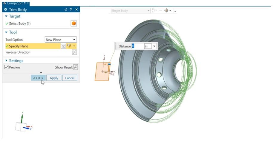
Figure 16: NX 2007 Feature Modeling 2D Outline– uses trim body to section the object in half using created 2D outline and Trim Body
Define functional regions of a part
Allows identification of multiple faces that represent a functional feature area of a component
Capabilities include:
o Group selected faces in a body
o Add attributes to Face Groups
o Face Groups can be carried through body links
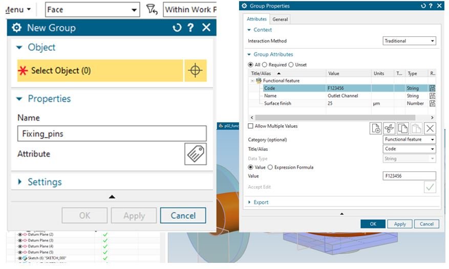
Figure 17: NX 2007 Face Groups – allows identification of multiple faces that represent a functional feature are of component
Example use cases
Allows identification of multiple faces that represent a functional feature area of a component
· Define attributes to a set of functional faces in the design
· Link through bodies and perform Booleans
· Extract attribute values in notes
· Visualize functional areas with simple selection
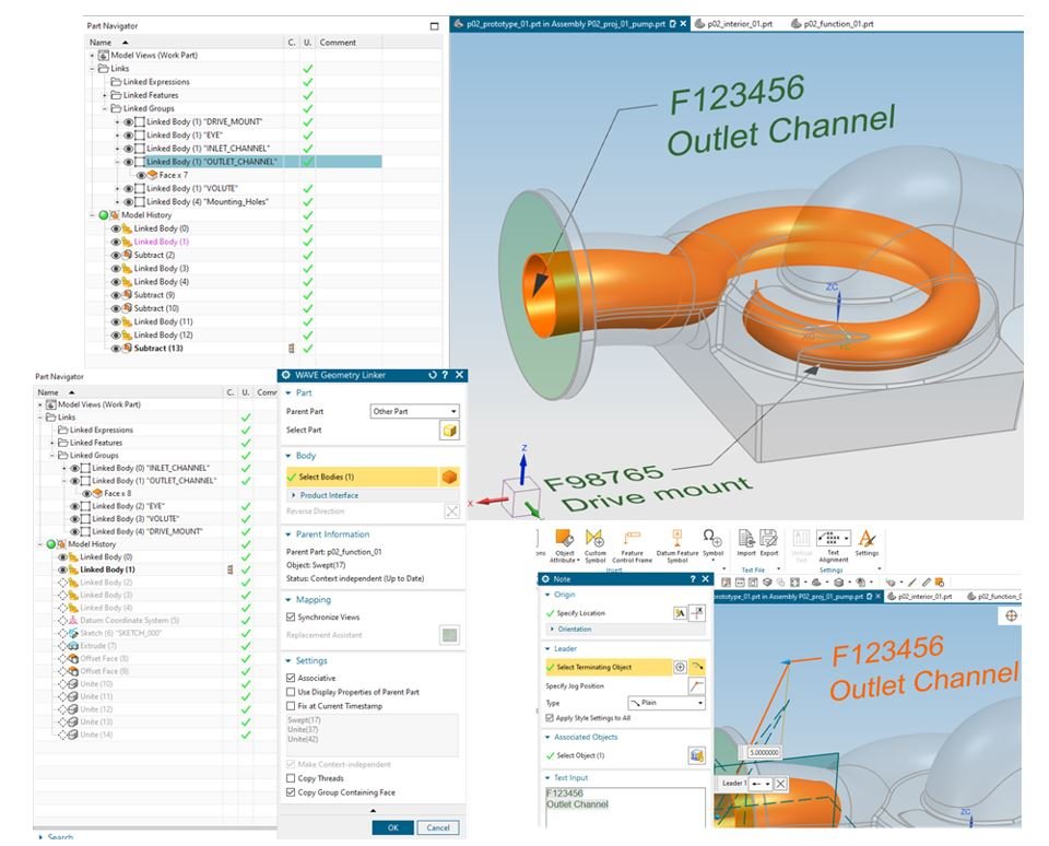
Figure 18: NX 2007 Face Groups – is the example of multiple faces that represent a functional feature are of component
Design preferences can now be found in search
The Modeling and Sketch preference dialogs have been converted to block-based dialogs, which enables Design preferences to be found in Search
Easily find Design preferences
· Can be found in global Search
· Can be searched within the Modeling/Sketch preferences dialogs also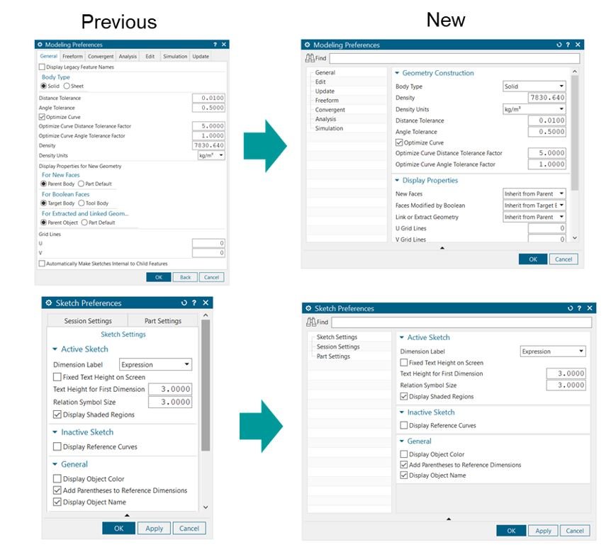
Figure 19: NX 2007 New Design Preference – shows new design preferences dialog
7) NX 2007 Realize Shape – Create a lattice-like subdivision body from non-manifold polylines
Tube Cage command accepts non-manifold polyline inputs and generates a subdivision body output in a single operation
NX Realize Shape enhancement to the Tube Cage command for “Branched Path” option
• Input non-manifold line or polyline to generate lattice-like subdivision body
• Control various parameters:
• Node Size
• Rod Size
• Falloff Distance
• Cross section and Rod segment counts
• End caps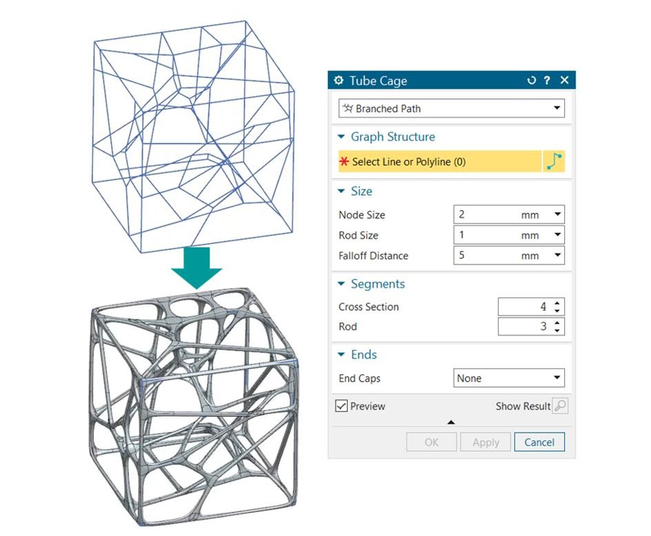
Figure 20: NX 2007 Realize Shape – shows lattice-like subdivision body from non-manifold polylines Tube Cage command accepts non-manifold polyline inputs and generates a subdivision body output in a single operation
8) NX 2007 Draw Shape – Visually convey and communicate aspects of the design prior to investing in 3D
NX Draw Shape provides the freedom to sketch concepts or design details creating fully associative and reusable curve geometry
New and improved user feedback driven capabilities include:
• Over-sketch on existing curves workflow
• Edit spline points number
• Snapping to curve endpoints
• Trim and Tangent control while drawing across the symmetry place
• Trim and Extend commands
• Keyboard accelerators
• Ctrl-D for Delete, Ctrl-J for Edit Object Display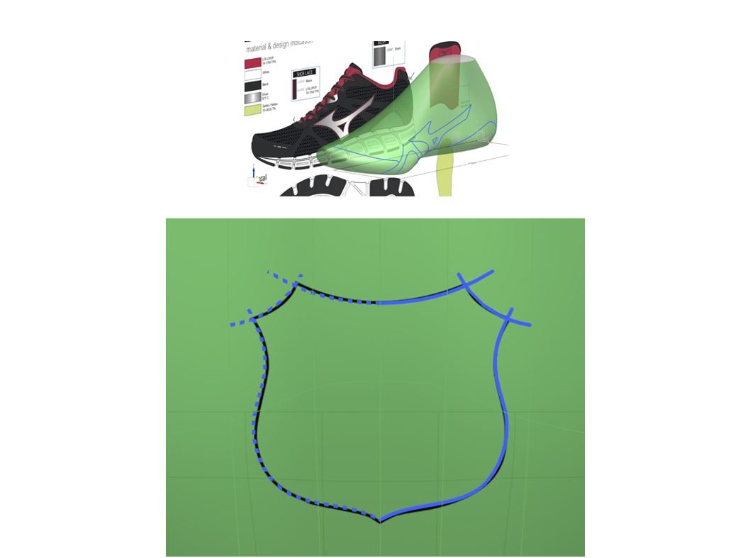
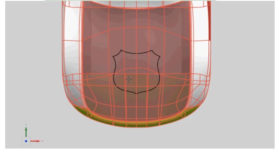
Figure 21: NX 2007 Draw Shape – improves to provide the freedom to sketch concepts or design details creating fully associative and reusable curve geometry
9) NX 2007 Topology Optimizer – Functional requirements driven topology optimization
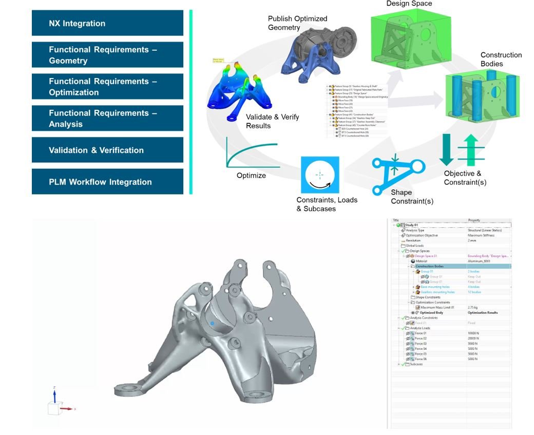 Figure 22: NX 2007 Topology Optimizer – new workflow to optimize the best character to your design
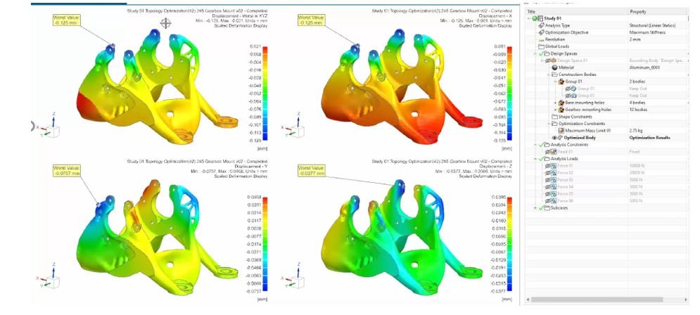
Figure 23: NX 2007 Topology Optimizer – new workflow and new improvement to optimize the best character to your design with CAE result
10) NX 2007 Design Space Explorer – use generative engineering to explore and optimize the design against multiple objectives
NX Design Space Explorer integrates Simcenter HEEDS for multi objective parameter optimization
Drive increased design efficiencies through CAD-Simulation integration
• Create a study to define the optimization problem with all parameters, constraints, and objectives
• Design variables are the parameters of the design which can be varied and given ranges
• Design constraints are the responses of the design that must remain within a certain range that defines a design as feasible
• Design objectives are the responses to meet the desired value or goal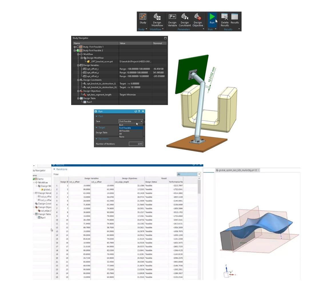
Figure 24: NX 2007 Design Space Explorer – integrates Simcenter HEEDS for multi objective parameter optimization
11) NX 2007 Lattice Structures Design – optimize lattice structure sizing from Simcenter3D stress results
Export Von Mises stresses from a Simcenter SOL200 lattice optimization as a Field and apply to the Lattice / Rod Thickness feature
Workflow:
• Optimize lattice diameters using Simcenter SOL200 design optimization
• Define minimum and maximum rod diameters
• Write Nastran solver syntax linked file
• Export outputs into a field format
• Apply optimized values to lattice
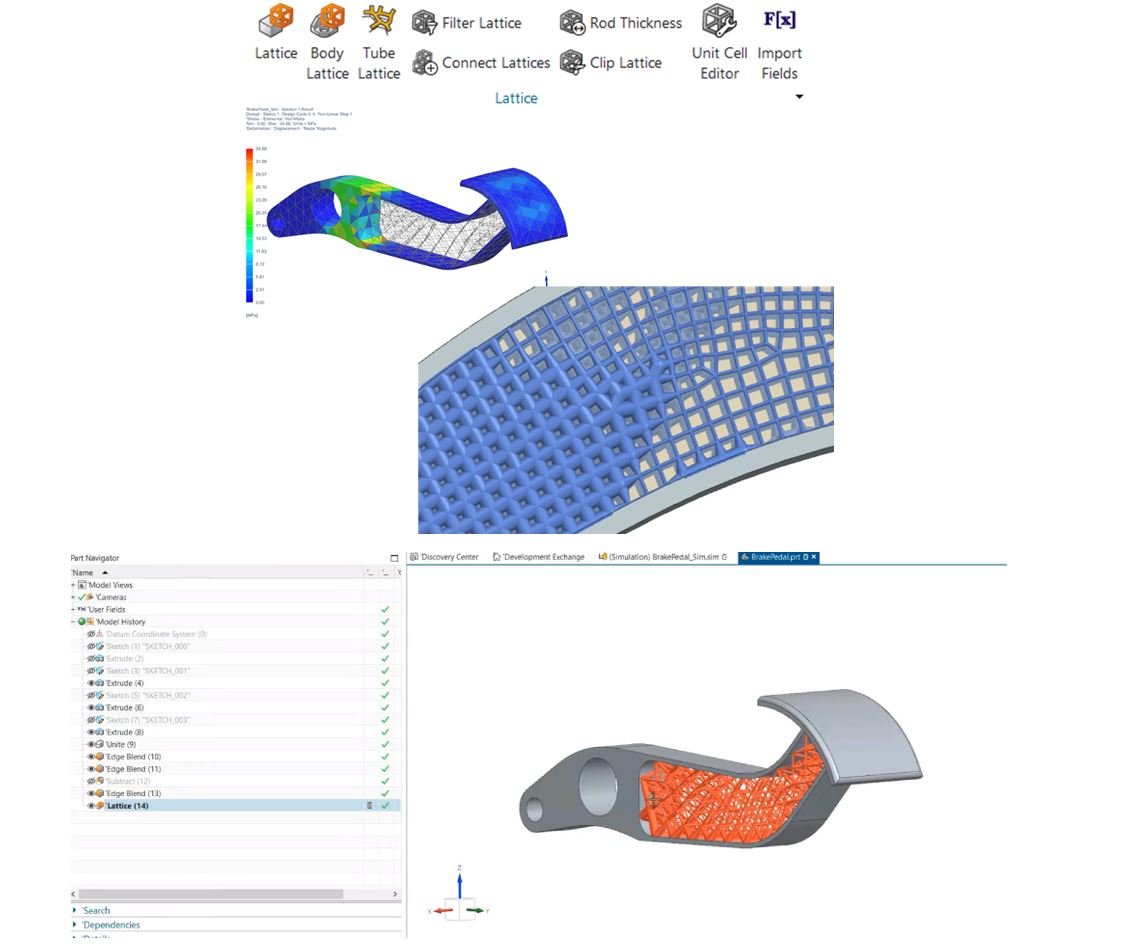
Figure 25: NX 2007 Lattice structure design – Optimize lattice diameters using Simcenter SOL200 design optimization
12) NX 2007 Algorithmic Modeling – Achieve a high degree of design robustness, templatization, and automation without requiring programming skills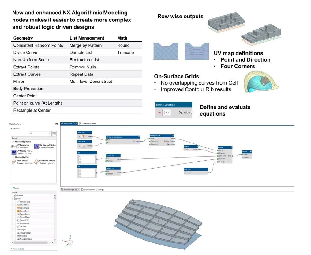
Figure 26: NX 2007 Algorithmic Modeling – New and enhanced NX Algorithmic Modeling nodes makes it easier to create more complex and robust logic driven designs
13) NX 2007 Implicit Modeling – Advanced structures modeling through operations that never fail
Powerful capabilities to create TPMS (Gyroid, etc.) and equation driven structures and combine them into part with robust shell, thicken, Boolean and blending capability that never fails
New and improved capability includes:
• New TPMS types: Lininoid & Split-P
• Fields driven variable thickness
• Cartesian and Cylindrical coordinates patterning
• Shell and Thicken quality improvements (Post EAP)
• Voxel size visualization
• Edit options: Parameters or Features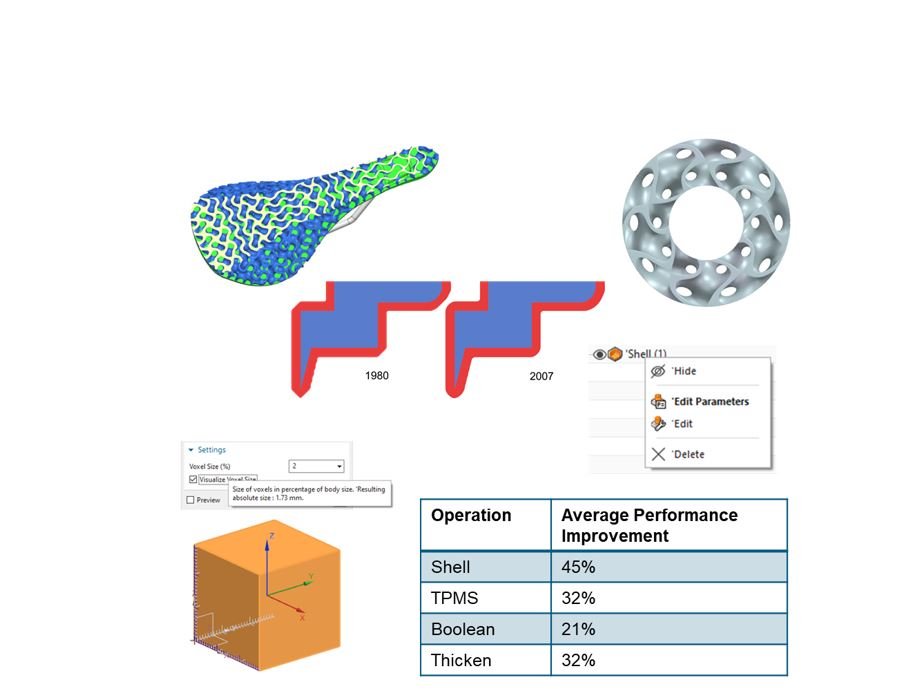
Figure 27: NX 2007 Implicit Modeling – Powerful capabilities to create TPMS (Gyroid, etc.) and equation driven structures and combine them into part with robust shell, thicken, Boolean and blending capability that never fails
")
")

